Monday, December 22, 2008

CCNA Lab: Copy to TFTP Server


Items of practical training certificates Cisco CCNA: Copy to TFTP Server

Start practicing: Link here Read more..!

CCNA Lab: RIP Routing


Items of practical training certificates Cisco CCNA: RIP Routing

Start practicing: RIP Routing Read more..!

CCNA Lab: IGRP Routing


Items of practical training certificates Cisco CCNA: IGRP Routing

Start practicing: Link here
Read more..!

CCNA Lab: Initial Switch Configuration


Items of practical training certificates Cisco CCNA: Initial Switch Configuration
Start practicing: Initial Switch Configuration Read more..!

CCNP_BCMSN Lab: Configuring a Distribution Switch


Items of practical training certificates Cisco CCNP_BCMSN (Building Cisco Multilayer Switched Networks)

Start practicing: Configuring a Distribution Switch Read more..!

Saturday, December 20, 2008

CCNA EIGRP LAB Question

Question:

After adding R3 router, no routing updates are being exchanged between R3 and the new location. All other inter connectivity and Internet access for the existing locations of the company are working properly.
The task is to identify the fault(s) and correct the router configuration to provide full connectivity between the routers.

Access to the router CLI can be gained by clicking on the appropriate host. All passwords on all routers are cisco.

IP addresses are listed in the chart below.

ccna_eigrp_sim

R1

Fa0/0: 192.168.77.33
S1/0: 198.0.18.6
S0/1: 192.160.60.25

R2

Fa0/0: 192.168.60.97
Fa0/1: 192.168.60.113
S0/0: 192.168.36.14

R3

Fa0/0: 192.168.77.34
Fa0/1: 192.168.60.65
Fa1/0: 192.168.60.81

R4

Fa0/0: 192.168.60.129
Fa0/1: 192.168.60.145
S0/1: 192.168.60.26

Answer and explanation:


We should check the configuration of the new added router first because it does not function properly while others work well. From the command line interface of R3 router, enter the show running-config command

ccna_eigrp_sim_show_run

From the output above, we know that this router was wrongly configured with an autonomous number (AS) of 22. When the AS numbers among routers are mismatched, no adjacency is formed.
(You should check the AS numbers on other routers for sure)

To solve this problem, we simply re-configure router R3 with the following commands:

R3>enable (you have to enter cisco as its password here)
R3#configure terminal
R3(config)#no router eigrp 22
R3(config)#router eigrp 212
R3(config-router)#network 192.168.60.0
R3(config-router)#network 192.168.77.0
R3(config-router)#no auto-summary
R3(config-router)#end
R3#copy running-config startup-config

Check R1 router with the show running-config command:

ccna_eigrp_sim_show_run_2

Notice that it is missing a definition to the network R3. Therefore we have to add it so that it can recognize R3 router

R1>enable (you have to enter cisco as its password here)
R1#configure terminal
R1(config)#router eigrp 212
R1(config-router)#network 192.168.77.0
R1(config-router)#end
R1#copy running-config startup-config

Now the whole network will work well. You should check again with ping command from router R3 to other routers!

Read more..!

CCNA: Cisco Certified Network Associate: Fast Pass


Organized by exam objectives, this is a focused, concise review guide that works hand-in-hand with any learning tool, including the Sybex CCNA: Cisco Certified Network Associate Study Guide, 6th and Deluxe editions.

The book will consist of four high-level chapters, each mapping to the four main Domains of the exam skill-set. The book will drill down into the specifics of the exam, covering the following:

* Designing Cisco internetworks
* Developing an access list
* Evaluating TCP/IP communication
* Configuring routers and switches
* Configuring IP addresses, subnet masks, and gateway addresses
* Performing LAN, VLAN, and WAN troubleshooting
* Understanding rules for packet control

The interactive CD contains two bonus exams, handy flashcard questions, and a searchable PDF of a Glossary of Terms.

The perfect companion to Sybex's CCNA: Cisco Certified Network Associate Study Guide, Sixth or Deluxe editions, or any CCNA study tool

The Perfect CCNA Preparation and Review Tool

Many candidates who complete a Study Guide or course also appreciate a review tool that helps them brush up on key topics. Sybex's CCNA Fast Pass, Third Edition, is that tool. This streamlined book hones in on critical information for the new CCNA exam 640-802, including network planning and design, implementation and operation, troubleshooting, and technology. Study, review, and practice with this practical study aid, then take the exam with confidence.

* Easy-to-use book is organized by exam objectives for quick review
* Flexible Fast Pass goes hand-in-hand with any learning tool on the market
* Exam Essentials in each chapter helps you zero in on what you need to know
* Book includes review questions, practice tools, and two practice exams
* Targeted and expert content from leading Cisco networking authority, Todd Lammle

Look inside for complete review coverage of all exam objectives for CCNA Exam 640-802


Download here (8.3M pdf) Read more..!

Friday, December 19, 2008

Cisco IOS access lists: 10 things you should know

Takeaway: Access control lists (ACLs) are a fundamental part of working with routers. How much do you know about managing these vital gatekeepers? David Davis lists 10 things every administrator should know about working with Cisco IOS ACLs.

People who read this, also read...
Playing with Cisco access lists
Use advanced parameters on your Cisco IOS ACLs
Traffic filtering with Cisco access lists: Why, how, and what to consider
Learn additional uses for Cisco IOS access control lists
Protect your network with the Cisco IOS Firewall
If you work with Cisco routers, you're more than likely familiar with Cisco IOS access control lists (ACLs). But that doesn't mean you know all there is to know about these important gatekeepers. Access lists are an integral part of working with routers, and they're vital to security.

Because ACLs are a fundamental part of router administration, I want to address 10 things you should know about working with these lists. If you're new to working with Cisco routers, this list offers a good foundation to get you started. But even if you've worked with Cisco routers for a while, it never hurts to review the basics—you might even learn something new.

So, without any further ado, here are 10 things you need to know about Cisco IOS access lists, beginning with the basic definition of an ACL.

What is an access control list?
In the Cisco IOS, an access control list is a record that identifies and manages traffic. After identifying that traffic, an administrator can specify various events that can happen to that traffic.

What's the most common type of ACL?
IP ACLs are the most popular type of access lists because IP is the most common type of traffic. There are two types of IP ACLs: standard and extended. Standard IP ACLs can only control traffic based on the SOURCE IP address. Extended IP ACLs are far more powerful; they can identify traffic based on source IP, source port, destination IP, and destination port.

What are the most common numbers for IP ACLs?
The most common numbers used for IP ACLs are 1 to 99 for standard lists and 100 to 199 for extended lists. However, many other ranges are also possible.

Standard IP ACLs: 1 to 99 and 1300 to 1999
Extended IP ACLs: 100 to 199 and 2000 to 2699
How can you filter traffic using ACLs?
You can use ACLs to filter traffic according to the "three P's"—per protocol, per interface, and per direction. You can only have one ACL per protocol (e.g., IP or IPX), one ACL per interface (e.g., FastEthernet0/0), and one ACL per direction (i.e., IN or OUT).

How can an ACL help protect
my network from viruses?
You can use an ACL as a packet sniffer to list packets that meet a certain requirement. For example, if there's a virus on your network that's sending out traffic over IRC port 194, you could create an extended ACL (such as number 101) to identify that traffic. You could then use the debug ip packet 101 detail command on your Internet-facing router to list all of the source IP addresses that are sending packets on port 194.

What's the order of operations in an ACL?
Routers process ACLs from top to bottom. When the router evaluates traffic against the list, it starts at the beginning of the list and moves down, either permitting or denying traffic as it goes. When it has worked its way through the list, the processing stops.

That means whichever rule comes first takes precedence. If the first part of the ACL denies traffic, but a lower part of the ACL allows it, the router will still deny the traffic. Let's look at an example:

Access-list 1 permit any
Access-list 1 deny host 10.1.1.1
Access-list 1 deny anyWhat does this ACL permit? The first line permits anything. Therefore, all traffic meets this requirement, so the router will permit all traffic, and processing will then stop.

What about traffic you don't specifically address in an ACL?
At the end of an ACL is an implicit deny statement. Whether you see the statement or not, the router denies all traffic that doesn't meet a condition in the ACL. Here's an example:

Access-list 1 deny host 10.1.1.1
Access-list 1 deny 192.168.1.0 0.0.0.255What traffic does this ACL permit? None: The router denies all traffic because of the implicit deny statement. In other words, the ACL really looks like this:

Access-list 1 deny host 10.1.1.1
Access-list 1 deny 192.168.1.0 0.0.0.255
Access-list 1 deny ANYCan I name an ACL?
Numbers—who needs numbers? You can also name your ACLs so you can more easily identify their purpose. You can name both standard and extended ACLs. Here's an example of using a named ACL:

router(config)# ip access-list ?
extended Extended Access List
log-update Control access list log updates
logging Control access list logging
resequence Resequence Access List
standard Standard Access List
router(config)# ip access-list extended test
router(config-ext-nacl)#
router(config-ext-nacl)# 10 deny ip any host 192.168.1.1
router(config-ext-nacl)# exit
router(config)# exit
router# show ip access-list
Extended IP access list test 10 deny ip any host 192.168.1.1What's a numbering sequence?
In the "old days," you couldn't edit an ACL—you could only copy it to a text editor (such as Notepad), remove it, edit it in notepad, and then re-create it. In fact, this is still a good way to edit some Cisco configurations.

However, this approach can also create a security risk. During the time you've removed the ACL to modify it, the router isn't controlling traffic as needed. But it's possible to edit a numbered ACL with commands. Here's an example:


router(config)# access-list 75 permit host 10.1.1.1
router(config)#^Z
router# conf t
Enter configuration commands, one per line. End with CNTL/Z.

router(config)# ip access-list standard 75

router(config-std-nacl)# 20 permit any
router(config-std-nacl)# no 10 permit 10.1.1.1
router(config-std-nacl)#^Z

router# show ip access-lists 75
Standard IP access list 75 20 permit any
router#How else can I use an ACL?
ACLs aren't just for filtering traffic. You can also use them for a variety of operations. Let's look at some of their possible other uses:

To control debug output: You can use the debug list X command to control debug output. By using this command before another debug command, the command only applies to what you've defined in the list.
To control route access: You can use a routing distribute-list ACL to only permit or deny certain routes either into or out of your routing protocol.
As a BGP AS-path ACL: You can use regular expressions to permit or deny BGP routes.
For router management: You can use an ACL to control which workstation or network manages your router with an ACL and an access-class statement to your VTY lines.
For encryption: You can use ACLs to determine how to encrypt traffic. When encrypting traffic between two routers or a router and a firewall, you must tell the router what traffic to encrypt, what traffic to send unencrypted, and what traffic to drop.
To wrap up this review, I'll leave you with one last tip: Don't forget to use remark statements in your ACLs. They'll come in handy when you have to troubleshoot something later.
Read more..!

Cisco Network Magic Pro 5.0.8282


Cisco has introduced a suite of network management software named Network Magic 5.0 . This tool will improve various network tasks like- connecting and sharing computers(content & printer), control computers on network while accessing Internet, connection repairing features, manage performance problem to provide optimize performance and many more. This tool run in the background and indicate/alert each time when new device connect to your network.

The Network Magic 5.0 suit provide the various functionality and provide capability to
* Connect and share content or a printer across a network
* Manage, monitor and control how computers on the network access the Internet
* Diagnose and repair connection and performance problems
* Optimize performance and reliability
* Track network history and usage through reporting capabilities
* Manage active connections and get status updates Control user
* Access and help secure the network from intruders

Features:
* Connect your devices together in minutes.
* Share Internet connections, printers and files.
* Protect your network with enhanced WPA security capabilities and status alerts.
* Repair your network and Internet connections to stay online and productive.
* Control access to the Internet and track online activity with remote desktop screenshots.
* And much more!

Download
Read more..!

Thursday, December 18, 2008

Lab 2, Modelling the CCNA Topology

 
This lab will teach you how to model the CCNA lab topology in a WAN scale.


Skills Required

 
This lab assumes that you have already completed lab 1.


The CCNA Lab Topology


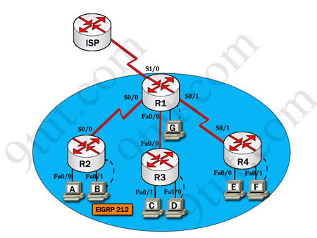
This is the topology used in the CCNA practical labs. Study the diagram to see the construct of this topology.


Creating the Project

 
Create a new project named ‘CCNA_Lab’ call the scenario ‘baseline’.
 
In the start-up wizard when choosing the network scale select the ‘choose from maps’ option and click ‘next’.
 
From the list of maps offered choose the ‘UK’ map and click ‘next’.
 
When selecting technologies for the project choose the Sm_Int_Model_List, ‘ethernet’ and ‘ethernet_advanced’ model groups and continue through the wizard until the project screen opens showing a map of the ‘UK’.
 

Placing Subnets on the Map

 
Select the ‘subnet’ object from the object palate and place four of them on the map as shown below.
 
Rename these subnets, Subnet_A, Subnet_B, Subnet_C and Subnet_DE. To do this ‘right-click’ over the Subnet and select the ‘Edit Attributes’ option then change the value in the name field and ‘click’ ‘Ok’.
 
It should now look like this.
 
 
The subnets are named after the routers they contain. Note how the subnet over London contains both routers D and E. On the lab topology these routers are connected together through a hub on a local network.
 

Subnet_A

 
To enter one of the subnets ‘double-click’ over it with the mouse. The project view will change to that of inside the subnet.
 
The first thing we need to do is place a router in the subnet. Change the object palate to the ‘Cisco’ Group.
 
Study the CCNA topology, the Lab_A router needs 2 Ethernet interfaces and one serial interface. We are going to use 1600 series Cisco routers in this topology, Find one with the appropriate interfaces, The CS_1605R_e2_s1 satisfies these demands, Place one inside the subnet then re name it Lab_A.
 
To rename the router ‘right-click’ and ‘Edit Attributes’ as with the subnet. Name the router Lab_A.
 
Now change the object palate back to the ‘CCNA-Lab-Baseline’ group and place 2 more subnets beside the router.
 
Rename the subnets ‘Switch_Subnet’ and ‘Hub_Subnet’ as shown below.
 
 
Now enter the Switch subnet by ‘double-clicking’ the icon.
 
Inside the switch subnet use the ‘configure rapid topology’ tool to create a star network topology the setting for which are shown below.
 
 
Rename the switch ‘Lab_A_Switch’.
 
Now go to the hub subnet and create another rapid configuration, this time using a 64-port Ethernet hub as the centre node and only 40 workstations. Don’t forget to rename the hub Lab_A_Hub.
 
Now return to subnet A. In the object palate select the 10BaseT link and connect the Router to each of the subnets. Before the link is created you will be prompted to select the node within each subnet to which it will connect. Connect through the nodes named Lab_A_Switch and Lab_A_Hub. See how that by naming the nodes we have made them easy to identify.
 
Subnet A should now like this:
 
 
Now go to Subnet B
 
This subnet requires a router with 2 serial interfaces and one Ethernet interface. Find the appropriate 1600 series router and place one in the subnet, re name it Lab_B. Now repeat the same rapid configuration as the in the lab B hub subnet. Name the hub Lab_B_Hub connect it to the router using a 10BaseT link. It should now look like this:
 
 
Now go to subnet B and repeat this topology remembering to name the Router Lab_B and the hub Lab_C_Hub.
 
To speed up this process you may wish to select all the nodes then use the ‘cut’ and ‘paste’ functions under the ‘Edit’ menu. The nodes can then be renamed.
 
Now go to subnet D.
 
This subnet will contain 2 routers, Lab D and lab E. Each requires 1 Ethernet interface and lab D requires 1 serial interface. Place the appropriate routers in the subnet then rename them Lab_D and Lab_E.
 
Now create another rapid configuration for a hub with 40 workstations as with the other subnets, rename the hub Lab_DE_Hub.
 
Now connect the lab D and E routers to the hub using 10BaseT links.
 
The finished subnet should look like this:
 
 
Now return to the map of the UK.
 
The next step is to connect the routers together. This will be done using 28K point-to-point protocol links.
 
 
Change the object panel to the links view. Now find the PPP 28K link and use it to connect each of the subnets. Each time a link is drawn you will be prompted to select the node to which the link attaches. Select the router for each subnet, the lab D router for subnet DE.
 
The completed network should look like this.


The Network we have Created

 
This network resembles that of a company with 4 offices operating in the UK. For this lab we will assume the company sells insurance over the phone. Subnet A is the head office. The head office is served by the 100 node switched network. This site also contains a sub office as subnets B,C and D. These are the call centres from where sales are made.
 
Our next step is to create some traffic for the network. In this scenario we will simulate the typical traffic used by a company. This is as follows:
 
Light e-mail – Used by staff to communicate with each other.
 
Light web browsing – An intranet is used to present staff with sales details.
 
Medium database access – An internal database will store the records used by staff to conduct day-to-day business operations.
 
A workgroup server will be attached to each hub to provide the local network with e-mail and intranet facilities.
 
A single server located at the head office in the Lab_A_switch subnet will provide database access to the entire company.
 

Adding Traffic to the Network

 
As you may remember from lab1 to add traffic to the network you need to define it through an application definition and a profile definition. From the CCNA_Lab-Baseline object palette find the two icons as pictured below and place them in the project workspace.


Not how this time we are not using pre-defined configs but we are going to define them ourselves.
 
Firstly we will define the application config telling Opnet which applications we are going to be using.
 
Right-click over the ‘Application Definition’ icon and choose to ‘Edit Attributes’ From the menu that appears.
 
Now click over the ‘value’ field next to the ‘Application Definitions’ attribute and select ‘edit’ from the popup menu.
 
The following window will appear:
 
 
In this table we will define our applications. As we want 3 types of application e-mail, web browsing and database we will need to enter 3 rows. Change the value in the rows box at the bottom left of the screen to 3. Three rows will now appear in the table.
 
 
We now have to enter our 3 applications.
 
For the first row ‘click’ the mouse over the description field and select ‘Edit’ from the drop down menu.
 
The first traffic we will define is the high load database access. In the window that appears locate the ‘database’ attribute and change the value to ‘Medium Load’ as pictured below.
 
 
Now click ‘OK’.
 
Rename the application Database, ‘Medium Load’ in the attributes table.
 
 
Now change the other fields to enter low load e-mail and web browsing. Note that web browsing comes under ‘http’ when selecting the application.
 
 
The finished application table should look like this, remember to name the applications.
 
Now click ‘Ok’.
 
You now need to enter the profile definition to generate application layer traffic. Right-click over the profile configuration and choose to ‘Edit Attributes’ from the menu that appears.
 
Click the mouse over the ‘value’ field for the ‘Profile Configuration’ attribute. A window will appear similar to that of the application definition table. This is the profile configuration table.
 
Change the number of rows to 3.
 
Change the profile names to ‘database, medium’, ‘web, light’ and ‘e-mail, light’.
 
Then edit the applications value and select the appropriate value from the applications we have defined. The finished applications table will look like this:
 
 
Click ‘Ok’ and exit to the network screen.
 

Creating Servers for the Network

 
Workgroup servers will be the source for all the traffic. There will be workgroup 4 servers, one in each of the subnets connected to the hubs using a 10BaseT link.
 
Each of the workgroup servers will need to be configured to tell Opnet which applications they will run. To reducer the amount of repetitive data entering we will set-up one server then copy and paste it into each location. This is possible because they are all going to serve the same applications.
 
The workgroup servers will provide e-mail and intranet access.
 
In subnet A, enter the hub subnet. In the object palate find the intermediate Ethernet server.
 
 
Now place one in the workspace and connect it to the hub using a 10BaseT link. Name the server Subnet_A_Server,
 
Right-click over the server and select the ‘Edit Attributes’ option.
 
In the attributes window click the mouse over the value field for the ‘Application: Supported Services’ attribute and select ‘Edit’ from the drop down menu.
 
You will now be presented with the application: supported services window. Change the number of rows to 2 then click over the name field and change the values to the applications for e-mail and web browsing that defined earlier. The window should now look like this:
 
 
Click ‘Ok’ and return to the subnet.
 
Now select the server node and from the ‘Edit’ menu select ‘copy’. Use the ‘Paste’ function to place a server in each subnet then connect them to the hubs using 10BaseT links.
 
Now place another server in the Switch subnet located in subnet A. use a 10BaseT link to connect it to the switch.
 
Now use the knowledge you have gained in this lab to configure the server to serve medium database access.
 
Finally before we can run our simulation we need to change the profiles for each of the Sm_Int_Wkstn’s to use the traffic we defined. To do this, enter one of the subnets and select all the Sm_Int_Wkstn nodes.
 
Now edit the attributes and check the box in the bottom left of the window to ‘Apply Changes to Selected Objects’. This will apply our changes to all the selected nodes.
 
Edit the ‘Application: Supported Services’ attribute and add 3 rows to the table to include all our traffic. It should look like this:
 
 
You will now have to repeat this for each of the subnets.
 

Running the Simulation

 
Right click on each server in turn and select to gather results for the server load (bits/sec) for each one.
 
Now select each of the point-to-point links between the routers and choose to collect results for the point to point utilisation in both directions.
 
Now run the simulation for 15 minutes.
 
Notice how long the simulation takes to run, this is because we are simulating a far heavier load of traffic than in lab 1 so Opnet takes a lot longer to calculate results.
 
How do you think the results for the server load an point to point utilisation will differ for each node and link? Why do you think this is?
 
The results for server load should resemble these.
 
 
As you can see from the results the load on the workgroup servers is far lower than that of the enterprise server. This is because they have to serve less data to fewer machines.
 
Now look at the results for point-to-point utilisation between subnets A and B, and subnets C and DE.
 
 
They should resemble this:
 
 
As you can see the utilization between subnets A and B is substantially higher than that between subnets C and DE. This is because all traffic for the enterprise server that is not going to subnet A crosses this link to supply subnets B, C and DE where only traffic to and from subnet DE crosses the link between subnets C and DE. Where the point-to-point utilisation reaches 100% the link is fully burdened with traffic. At these times traffic will take a long time to traverse the links.
 

Extension Work

 
Clear the traffic profiles you have created and set-up the network to use different traffic types. Investigate the demands of the varying traffic types place on the network.
Read more..!

PacketTrap Ping Scan 1.1.3301

PacketTrap Ping Scan is a FREE utility that sends ICMP ECHO requests across a network and rapidly builds a spreadsheet of responding nodes. DNS lookup information may optionally be provided by Ping Scan for each responding address. Follow the link and free download PacketTrap Ping Scan now.
Download link 1: Download now
Download link 2: Download now
Read more..!